Views: 0 Author: Site Editor Publish Time: 2026-10-07 Origin: Site
Imagine a municipal water network bursting beneath a busy intersection simply because a contractor miscalculated the dimensional ratio of the installed conduit. When designing a robust piping system or setting up a modern plastic pipe machine line, understanding high-density polyethylene wall thickness is strictly non-negotiable. Engineers globally recognize HDPE pipes for their exceptional durability, flexibility, and chemical resistance. These inherent properties make them the primary material choice for water supply, high-pressure gas distribution, and heavy industrial drainage.
However, a pipe will only withstand internal fluid pressure and external environmental loads if the mathematical correlation between its outside diameter and its wall profile is exact. This critical metric is defined by the Standard Dimension Ratio, commonly abbreviated as SDR. We will systematically break down the essential dimensional charts and explain the engineering principles behind calculating SDR. Furthermore, we will explore industry-specific requirements and examine the precise production machinery needed to manufacture flawless polymer pipes.
Key Takeaways
SDR is the Key Metric: The Standard Dimension Ratio represents the geometric ratio of the pipe outside diameter to its minimum wall thickness. A lower SDR value indicates a thicker wall and a higher pressure rating.
Accurate Charts are Essential: Standardized dimensional charts ensure engineering projects comply with global ISO 4427 and ASTM F714 standards for both metric and imperial measurements.
Application Dictates Thickness: Specific operational environments demand different profiles. High-pressure gas lines typically require SDR 9 or SDR 11, whereas gravity-fed sewer systems safely utilize SDR 26 or SDR 32.
Production Precision Matters: Manufacturing conduits with consistent dimensional accuracy requires advanced extrusion machinery, precise vacuum calibration, and multi-stage cooling systems to prevent polymer sagging.
The primary function of any pressurized piping system is to safely contain and transport fluids without rupturing. In fluid dynamics, the thickness of the pipe wall directly dictates its nominal pressure rating (PN), defined as the maximum allowable operating pressure in bar at 20°C. When water or gas pumps through a pipeline, it exerts outward radial stress against the inner walls. Engineers refer to this as hoop stress. A thicker wall provides more cross-sectional material to distribute and absorb this force. When the wall is too thin for the operational pressure, the material yields under circumferential stress. The pipe balloons. Eventually, it bursts. By adhering to precise thickness standards, field engineers ensure the infrastructure maintains its structural integrity over an intended 50-to-100-year lifespan.
Beyond internal fluid pressure, polyethylene pipes must withstand significant external mechanical forces. This is especially true when they are buried deep underground. The wall acts as a structural shield against external load-bearing pressures. These include the dead weight of backfill soil, dynamic traffic loads from roadways above, and fluctuating groundwater tables. An adequate profile also protects the pipeline from environmental stress cracking caused by concentrated external loads. Sharp rocks or uneven trench beds pressing against the exterior can cause catastrophic point failures. Consequently, in trenchless installations, a robust wall is mandatory. It must withstand the immense tensile pulling forces required to drag the conduit through a rocky subterranean borehole.
Adding material increases strength, but it introduces a necessary engineering trade-off regarding fluid flow capacity. The nominal outside diameter, known as OD, remains constant for a specific pipe size. Therefore, increasing the wall thickness inherently reduces the internal diameter, or ID. A smaller internal cavity restricts the cross-sectional flow area. This slightly lowers the volumetric flow rate and increases fluid friction. Planners must carefully calculate the optimal balance. They need to achieve the required pressure rating while maintaining sufficient flow capacity to avoid overworking the system pumps.
The Standard Dimension Ratio is an internationally recognized method for rating pressure pipes. It describes the correlation between physical dimensions and pressure-bearing capability. The formula is straightforward. SDR equals the Nominal Outside Diameter divided by the Minimum Wall Thickness.
In practical terms, imagine you are out in the field working with a conduit that has an outside diameter of 110mm and an SDR rating of 11. You can easily calculate the required minimum thickness by rearranging the formula. Dividing 110mm by 11 results in a minimum wall of 10.0mm. This proportional relationship guarantees that a 32mm pipe and a 630mm pipe with the identical SDR will be capable of handling the exact same internal water pressure.
Contractors often use SDR and Dimension Ratio interchangeably on job sites, but there is a distinct technical difference. SDR refers to a specific, standardized series of preferred numbers adopted by the International Organization for Standardization and the American Society for Testing and Materials. These preferred ratios include 9, 11, 13.6, 17, 21, and 26. Dimension Ratio, conversely, is simply the calculated ratio of any outside diameter to wall thickness, even if the resulting number does not fall into the standardized preferred series.
The dimension ratio directly dictates the Nominal Pressure rating. This represents the maximum allowable operating pressure in bars at 20 degrees Celsius. However, this rating also depends heavily on the specific grade of raw polymer used. For modern PE100 materials, the relationship is highly standardized. SDR 9 maps to PN 20, which is 20 bar or 290 psi. SDR 11 aligns with PN 16, equating to 16 bar or 232 psi. Moving up the ratio scale, SDR 17 corresponds to PN 10, and SDR 26 drops to PN 6.
To facilitate accurate engineering design and manufacturing calibration, standard dimension charts are utilized globally. Below are the reference frameworks for both metric and imperial measurements.
This table outlines the minimum thickness in millimeters for common metric outside diameters based on ISO 4427 specifications for PE100 materials.
Outside Diameter in mm | SDR 26 - PN6 | SDR 21 - PN8 | SDR 17 - PN10 | SDR 13.6 - PN12.5 | SDR 11 - PN16 | SDR 9 - PN20 |
|---|---|---|---|---|---|---|
32 | - | - | 2.0 | 2.4 | 3.0 | 3.6 |
63 | 2.5 | 3.0 | 3.8 | 4.7 | 5.8 | 7.1 |
110 | 4.2 | 5.3 | 6.6 | 8.1 | 10.0 | 12.3 |
160 | 6.2 | 7.7 | 9.5 | 11.8 | 14.6 | 17.9 |
250 | 9.6 | 11.9 | 14.8 | 18.4 | 22.7 | 27.9 |
400 | 15.3 | 19.1 | 23.7 | 29.4 | 36.3 | 44.7 |
In North America, pipelines are frequently sized according to Iron Pipe Size or Ductile Iron Pipe Size standards under ASTM F714. The following table represents the minimum wall dimension in inches for standard IPS sizes.
Nominal IPS Size | Outside Diameter in inches | SDR 17 - Thinner | SDR 11 - Standard | SDR 9 - Thicker |
|---|---|---|---|---|
2" | 2.375 | 0.140 | 0.216 | 0.264 |
4" | 4.500 | 0.265 | 0.409 | 0.500 |
6" | 6.625 | 0.390 | 0.602 | 0.736 |
8" | 8.625 | 0.507 | 0.784 | 0.958 |
12" | 12.750 | 0.750 | 1.159 | 1.417 |
The foundational step in selecting the correct ratio is establishing the maximum sustained internal pressure of the system. Do not just look at the standard working pressure. You must account for potential surges, water hammer effects, and transient spikes. Planners calculate the Maximum Allowable Operating Pressure and select a rating that offers a safety factor well above this peak value.
The raw material grade significantly impacts structural requirements. PE100 is a higher-density, more crystalline polymer than the older PE80 standard. It possesses a higher Minimum Required Strength of 10.0 MPa compared to the 8.0 MPa of PE80. Because PE100 is inherently stronger, project managers can achieve the exact same pressure rating using a thinner profile. Utilizing PE100 reduces material volume, lowers procurement costs, and increases the internal flow capacity.
Engineers calculate standard ratings based on a baseline fluid temperature of 20 degrees Celsius. If the conduit will transport higher-temperature fluids, the plastic softens slightly. This reduces its pressure-bearing capacity. In these scenarios, you must apply temperature derating factors, often necessitating a shift to a lower SDR to compensate. Additionally, consider the installation method. When a drilling rig pulls a 500-foot continuous segment of HDPE through rocky subterranean soil during Horizontal Directional Drilling, the pipe is subjected to severe abrasive and tensile forces. Thicker walls are mandatory to prevent the conduit from elongating or snapping during pullback.
Municipal potable water networks require materials that ensure a sterile, leak-free environment over vast distances. For these critical applications, SDR 11 and SDR 17 are the industry standards. Engineers typically deploy SDR 11 for main distribution lines that endure high pump pressures. SDR 17 is often sufficient for secondary residential branch lines.
Unlike pressurized water mains, sanitary sewers and storm drainage systems generally operate via gravity flow. Internal pressure is negligible. Gravity sewer lines frequently utilize SDR 26 or SDR 32, which feature significantly thinner profiles. Because these conduits are buried deep underground, the engineering focus shifts entirely from internal pressure resistance to external ring stiffness. This ensures the circular shape is maintained under heavy soil compaction.
The mining and dredging sectors subject piping systems to extreme mechanical abuse. Transporting highly abrasive slurries composed of rock, sand, and corrosive wastewater rapidly erodes standard materials. To combat rapid internal wear, these operations mandate custom, ultra-thick dimensions. They frequently utilize SDR 9 or even SDR 7.4. The massive wall provides a sacrificial wear layer, exponentially extending the maintenance lifecycle.
The global infrastructure sector is currently witnessing a significant shift in how polyethylene materials are specified and manufactured. One major trend is the rapid adoption of PE100-RC, which stands for Resistance to Crack. This advanced polymer compound offers exponentially higher resistance to slow crack growth. It allows contractors to install pipes without traditional sand bedding, even in rocky terrains. To keep up with this material evolution, manufacturers are actively upgrading their HDPE pipe manufacturing equipment to accommodate the unique melt flow characteristics of these next-generation resins.
Driven by extreme weather events and the need for upgraded stormwater management, there is a surging demand for large-diameter HDPE pipes extending beyond 1200mm. Producing these massive conduits while maintaining strict SDR tolerances requires highly automated extrusion lines equipped with advanced thermal regulation. This minimizes human error and maximizes output efficiency across the entire production floor.
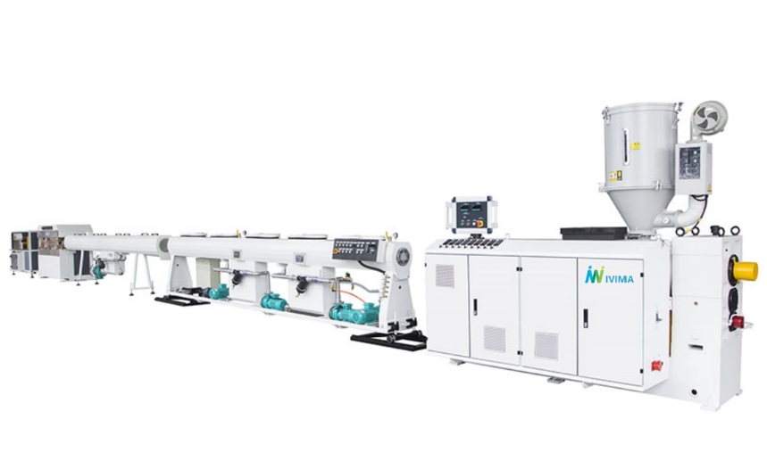
Achieving and maintaining exact dimensional tolerances during manufacturing is an intricate thermodynamic process that begins at the extruder. The raw polyethylene pellets are melted and pushed through an annular die to form the initial shape. Any fluctuations in melt temperature, polymer homogeneity, or screw RPM will immediately cause variations in the profile. Investing in advanced extrusion machinery is critical. Modern high-efficiency single-screw extruders often feature a 38:1 L/D ratio. This extended barrel length ensures consistent melt pressure and uniform material distribution. Coupled with Siemens PLC control systems, operators can maintain exact standard compliance at high production speeds.
Once the molten polymer exits the extrusion die, it enters the vacuum calibration tank. This stage is vital for defining the final outside diameter. The calibration sleeve uses a vacuum environment to pull the soft, semi-molten tube outward against a sizing ring while chilled water instantly freezes the outer skin. If the vacuum pressure is inconsistent, the outside diameter will fluctuate. This makes it impossible to achieve a uniform profile across the circumference.
Polyethylene is an excellent insulator. It takes a significant amount of time for heat to transfer from the inner core of a thick wall to the cooled outer surface. During this phase, gravity acts upon the molten polymer. Without proper intervention, the heavy, semi-liquid plastic will slowly drip or sag toward the bottom. This results in a conduit that is out of tolerance, meaning it is too thick at the bottom and dangerously thin at the top. Top-tier extrusion lines utilize intensive, multi-stage spray cooling tanks to solidify the entire matrix rapidly and uniformly.
To guarantee that every meter meets ISO and ASTM specifications, modern manufacturing facilities integrate inline ultrasonic scanners. Positioned immediately after the vacuum calibration or cooling tanks, these non-destructive sensors rotate 360 degrees. They continuously measure the dimensions in real-time. This automated monitoring instantly alerts the operator if any deviation from the target parameters is detected.
Dimensional stability relies heavily on controlling the exact volume of raw material entering the process. Advanced gravimetric dosing systems weigh the raw pellets and additives as they feed into the extruder hopper. By synchronizing the material weight per meter with the line haul-off speed, the controller eliminates human error. This guarantees the correct volume of plastic is used, preventing material waste and ensuring structural consistency.
Inline monitoring is always supplemented by rigorous post-production laboratory testing. Technicians cut samples from extruded batches and subject them to strict compliance tests. During the hydrostatic pressure test, the sample is filled with water, pressurized to its maximum threshold, and held at elevated temperatures. This verifies that the pipe performs exactly as engineered under extreme stress conditions.
Getting the HDPE pipe wall thickness right is absolutely critical for the safety and longevity of major infrastructure projects. Whether you are an engineer consulting an SDR chart to design a high-pressure municipal water network, or a facility manager calibrating an extrusion line to manufacture PE100 conduits, precision is everything. Proper thickness prevents catastrophic failures, ensures adequate flow rates, and withstands harsh environmental loads. For manufacturers, achieving this exactness relies heavily on utilizing top-tier extrusion technology and implementing stringent quality control measures. If you are looking to upgrade your production capabilities, exploring a precision-engineered extrusion line from IVIMA Plas will ensure you deliver defect-free, standard-compliant piping to the global market.
SDR 11 indicates that the pipe outside diameter is exactly 11 times its minimum wall thickness. It is one of the most common standard dimension ratios globally. For modern PE100 materials, an SDR 11 pipe provides a nominal pressure rating of PN16, which is approximately 232 psi. This makes it highly suitable for high-pressure potable water distribution and industrial gas lines.
The inside diameter can be determined using a straightforward mathematical formula: ID equals Outside Diameter minus two times the Wall Thickness. Because manufacturing tolerances generally allow for a slightly thicker profile than the absolute minimum specified, the actual ID may be marginally smaller than the theoretical calculation.
A lower SDR number mathematically indicates a thicker pipe wall relative to its outside diameter. Because the wall contains more structural material, a lower SDR results directly in a higher internal pressure rating and increased resistance to external mechanical loads.
Uneven wall thickness during manufacturing is typically caused by mechanical die misalignment, uneven thermal cooling, or inconsistent raw material throughput from the extruder. Uneven cooling specifically leads to polymer sagging. Upgrading the vacuum calibration and multi-stage cooling sections of the plastic pipe machine generally resolves these concentricity issues.
While you physically can, it is highly inefficient. PE100 is a structurally superior polymer with a higher minimum required strength than PE80. Therefore, to achieve the exact same operational pressure rating, PE100 requires a thinner wall. Utilizing PE100 allows for higher SDRs, which reduces raw material costs and increases the internal flow capacity.
The maximum pressure depends entirely on the SDR and the material grade. For standard PE100 materials, an SDR 7.4 pipe can handle up to PN25, which translates to 25 bar or roughly 362 psi. However, special applications may require custom profiles for even higher stress environments.
Standard pressure ratings are calculated at a baseline of 20 degrees Celsius. As the temperature of the fluid increases, the polyethylene material softens, which lowers its tensile strength. Engineers must apply a temperature derating factor. For example, water flowing at 40 degrees Celsius will significantly reduce the maximum allowable operating pressure, requiring a thicker pipe wall to compensate.